
Applies to: NHP-P100 (1 Door Controller), NHP-P200 (2 Door Controller), OnCAFE-compatible configurations
Summary
This article describes the process for wiring peripherals to the NHP-P100 and NHP-P200 controllers.
Each NHP Controller supports the following components:
- Card Reader (Wiegand or OSDP)
- Electric Lock (Fail-Safe or Fail-Secure)
- REX Sensor (Request to Exit)
- Door Contact (DPS)
- Optional: Fire Alarm Interface (FAI), Auxiliary Input (AUX IN)
Prerequisites
Before wiring peripherals:
- Match cable type to the distance and voltage drop requirements.
- Confirm wire colors or terminal block pinout against device manuals.
Label cables and use strain reliefs to prevent troubleshooting issues later.
Wiring a Card Reader
The card reader identifies users via physical (Card/Fob), PIN code, or mobile credentials (NFC/BLE) and transmits credentials data to the controller/panel.
To wire a card reader, use shielded 22/6 cable for typical Wiegand wiring.
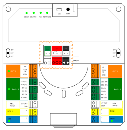
Wire the card reader (Wiegand or OSDP) as follows:
- Red - RD 12V+ (Power to Reader)
- Black - RD GND (Power Ground)
- Green - DO(A) (Wiegand D0 or RS-485 A)
- White - D1(B) (Wiegand D1 or RS-485 B)
- Brown - LED (Optional - Control Reader LED)
- Orange - BUZ (Optional - Control Reader Buzzer)
Wiring an Electric Lock
The electric lock secures or releases the door.
To wire an electric lock:
- Identify the Positive Lock Conductor.
- Determine whether the lock to be connected is Fail-Safe (NC) or Fail-Secure (NO).
- Identify the negative ground wire.
- Use 18/2 or 18/4 cable for power and control wiring.
- Set the 3-position switch to match lock voltage requirements.
Center - Dry Contact (Relay Only)
Up - 24VDC Output
Down - 12VDC Output
Wiring a REX Sensor
The REX Sensor detects motion or proximity to request exit.
To wire a REX Sensor, use 22/4 cable.
Wire the REX Sensor as follows:
- Red - 12V Out (REX Power +)
- Black - GND (REX Power -)
- Green - REX + (Dry Contact NO Output)
- White - REX - (Dry Contact Return)
IMPORTANT: Ensure the REX has a dry contact that closes on motion.Wiring a Door Contact
The door contact monitors the door status (open/closed).
To wire a door contact, use a minimum of 22/2 or 22/4 cable.
Wire the door contact as follows:
- White - DPS + (Input +)
- Black - DPS - (Input -)
Wiring Auxiliary Inputs
AUX IN
- (+) - Auxiliary Sensor Input
- (-) - Ground
FAI (Fire Alarm Interface)
- (+) - Alarm Activation Input
- COM - Common Terminal
- (-) - Reset Input
Powering the Controller
Power Input (DC IN)
The NHP Controller can be powered by one of the following methods:
- PoE++ (Power over Ethernet – IEEE 802.3bt)
- PoE++ (IEEE 802.3bt)
This is recommended for optimal performance and sufficient current to support locks, readers, and onboard electronics.
- Power is supplied through the network port (RJ-45).
Direct 12VDC or 24VDC Input
If not using PoE++, the controller can be powered using a dedicated DC power supply.
Connect the DC IN terminals as follows:
- (+) - 12VDC or 24VDC Input
- (–) - Ground
IMPORTANT: Confirm the power supply matches the controller’s rated voltage.Redundant Power
Either PoE++ or DC IN can act as a backup if one power source fails.
IMPORTANT: Verify the power source provides enough current for all
connected peripherals (locks, readers, sensors, and other connected devices).